
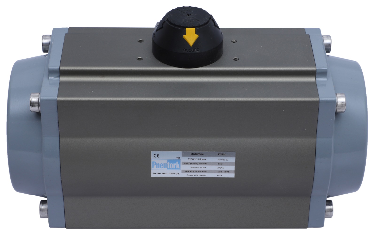
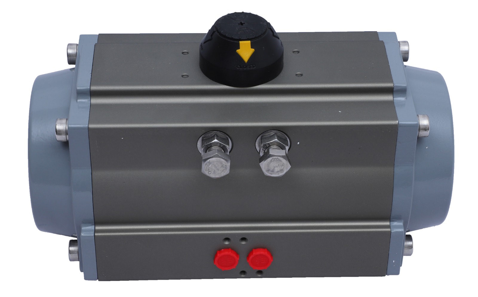
A pneumatic rack and pinion actuator is a type of device used in industrial automation and control systems to convert the linear motion of compressed air into rotary motion. This actuator is commonly employed to control valves in various applications, such as in the oil and gas industry, chemical processing plants, water treatment facilities, and other industrial settings.
Here's a brief explanation of the key components and working principle of a pneumatic rack and pinion actuator:
The rack is a linear gear with teeth cut into its surface. It typically moves back and forth linearly.
The pinion is a small gear that engages with the teeth of the rack. When the pinion rotates, it causes the rack to move linearly.
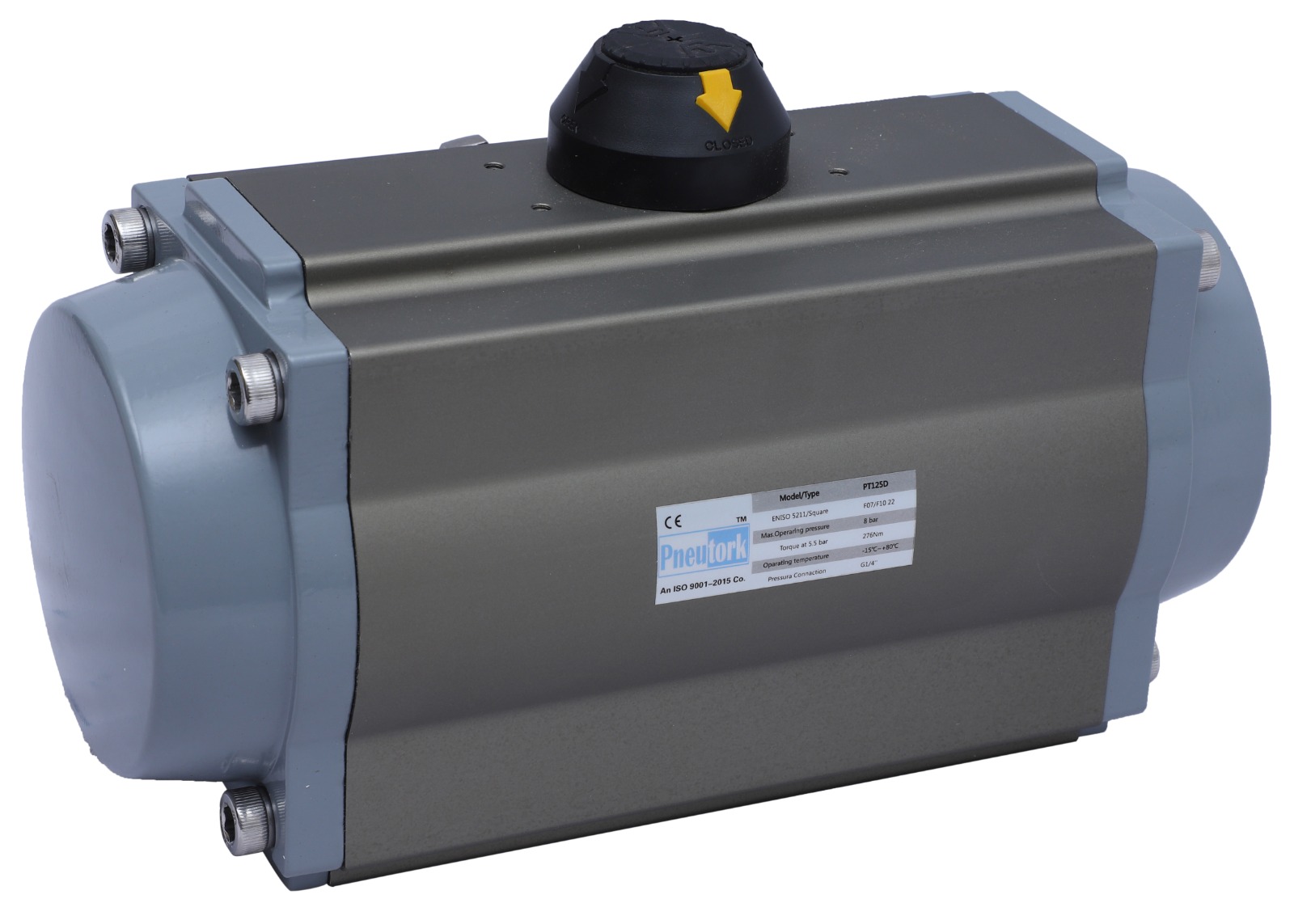
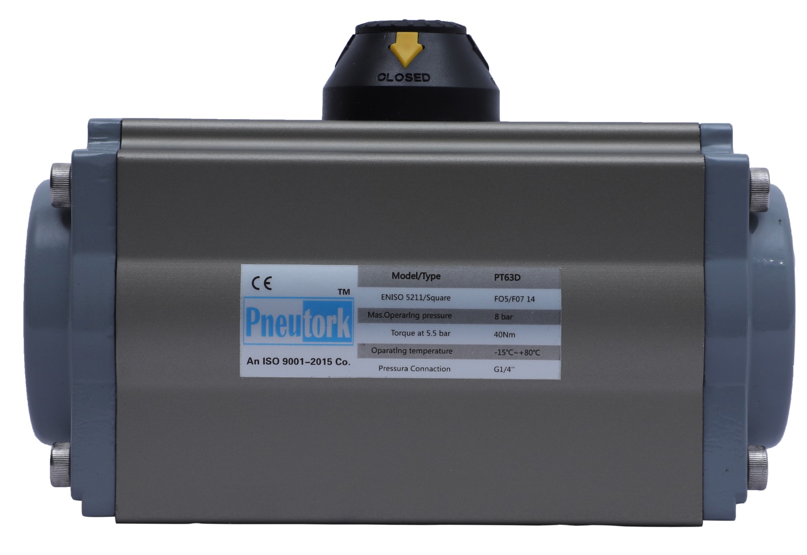
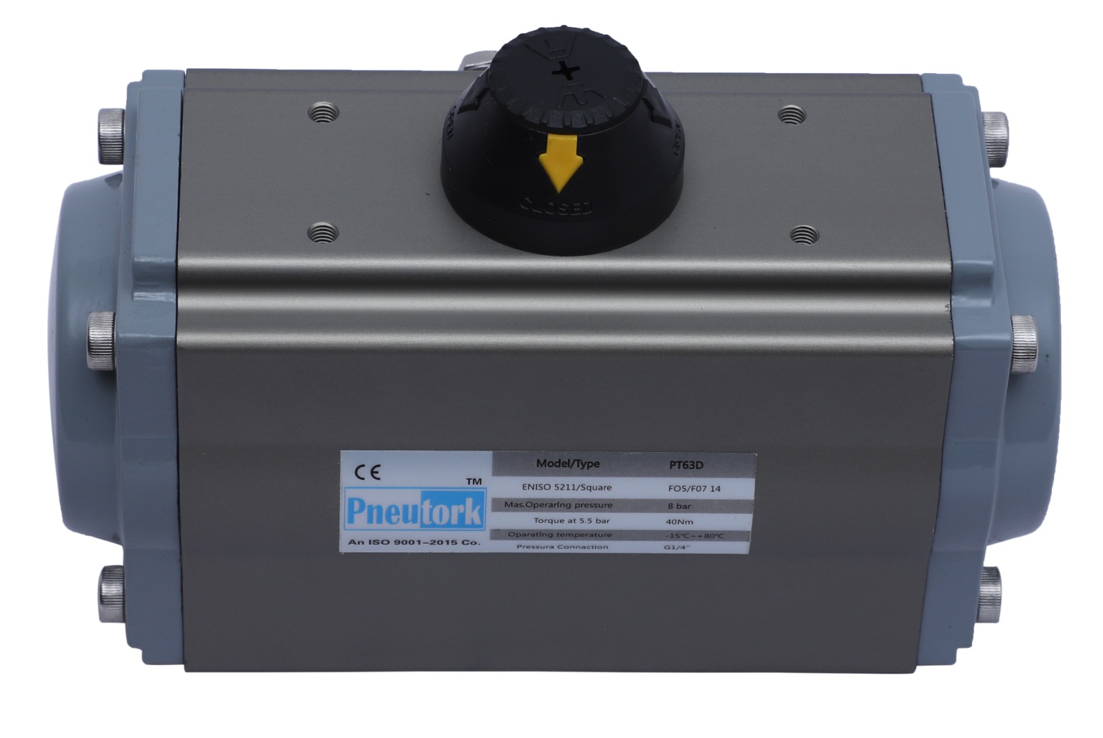
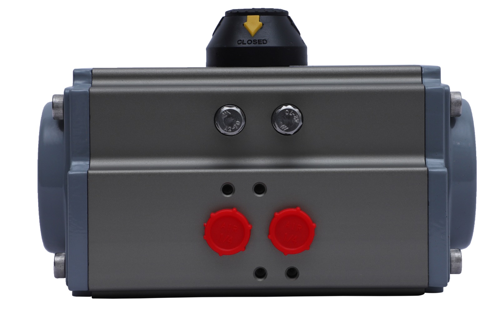
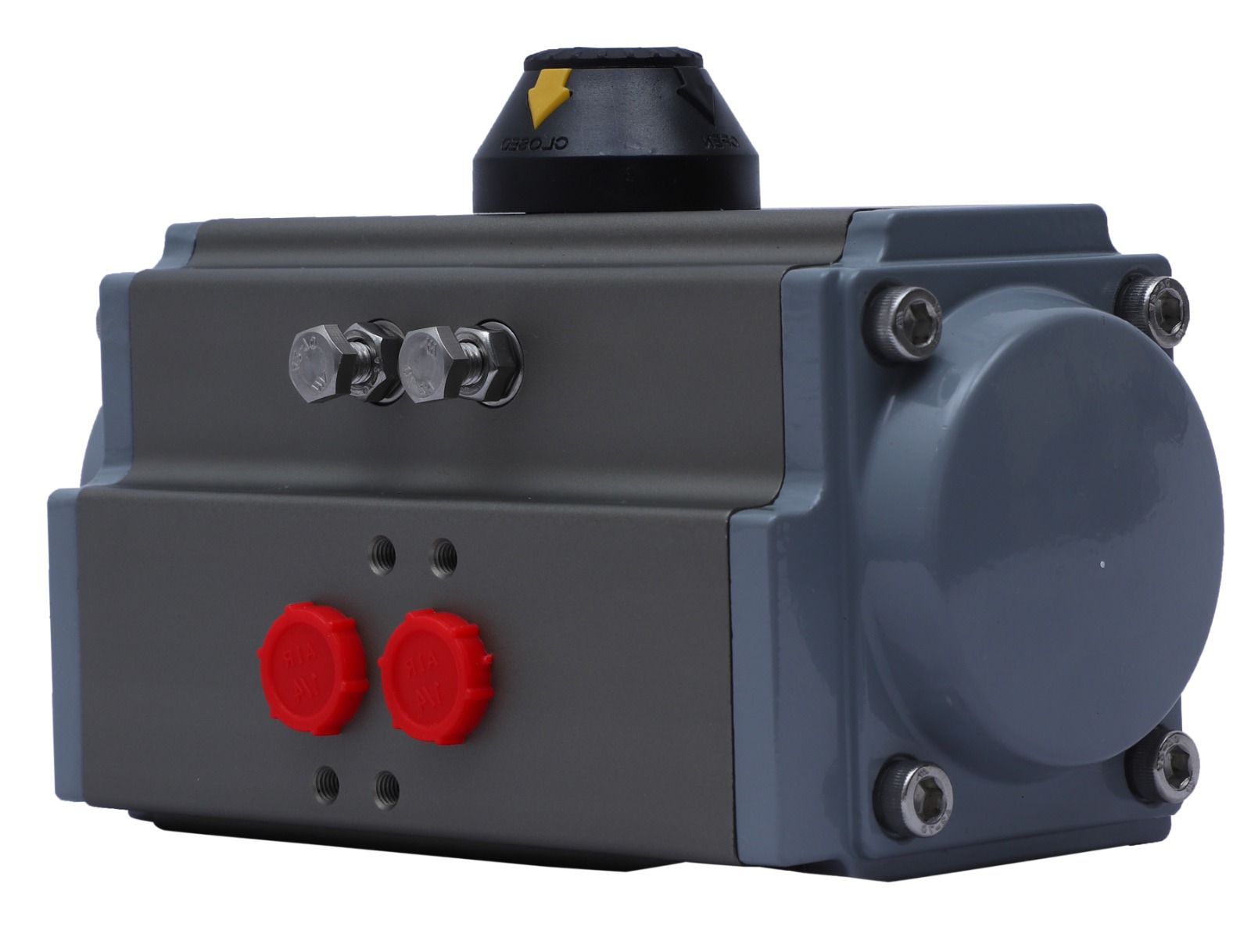
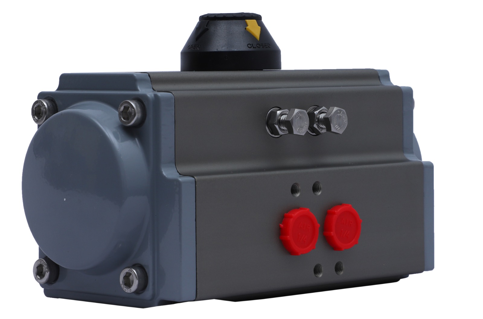
The actuator body houses the rack and pinion mechanism, providing support and alignment for the components.
The pneumatic cylinder is a crucial part of the actuator. It contains a piston that moves back and forth inside the cylinder when compressed air is introduced. The movement of the piston is what drives the rack and pinion mechanism
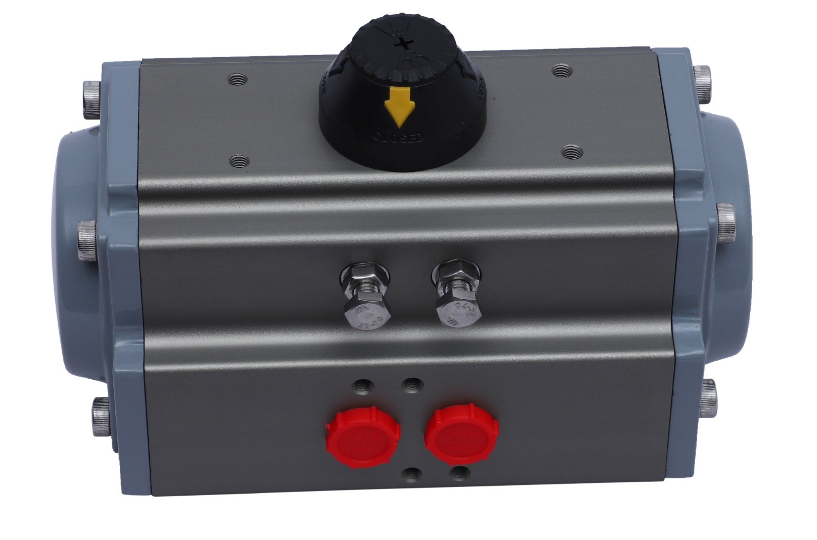
Compressed air is supplied to the pneumatic cylinder through an inlet. The outlet allows the air to be exhausted
A directional control valve is used to control the flow of compressed air to the pneumatic cylinder. By manipulating the valve, operators can control the direction of movement of the actuator (extend or retract).
When compressed air is directed to one side of the piston inside the pneumatic cylinder, it pushes the piston, causing the rack and pinion mechanism to move linearly. This linear motion is then converted into rotary motion, rotating the output shaft of the actuator
When compressed air is directed to the other side of the piston, it pulls the piston back, reversing the linear motion of the rack and pinion mechanism and causing the output shaft to rotate in the opposite direction.
Pneumatic rack and pinion actuators are known for their simplicity, reliability, and quick response time. They are commonly used in applications where a fast and efficient valve control is required.
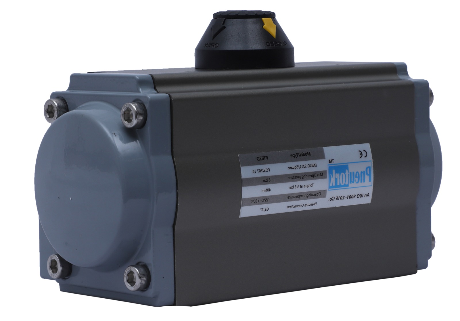
| Indicator : | The indicator confirms to VID/VIE3845 namur standard, which is convenient for installing limit switch, positioned and other accessories |
|---|---|
| Output Shaft : | The design of the one-body forging and pressing output shaft of nickel-plated alloy steel is in accordance with NAMUR, ISO5211 and DIN3337 standard. Special standards can be customized accordin to the customer. |
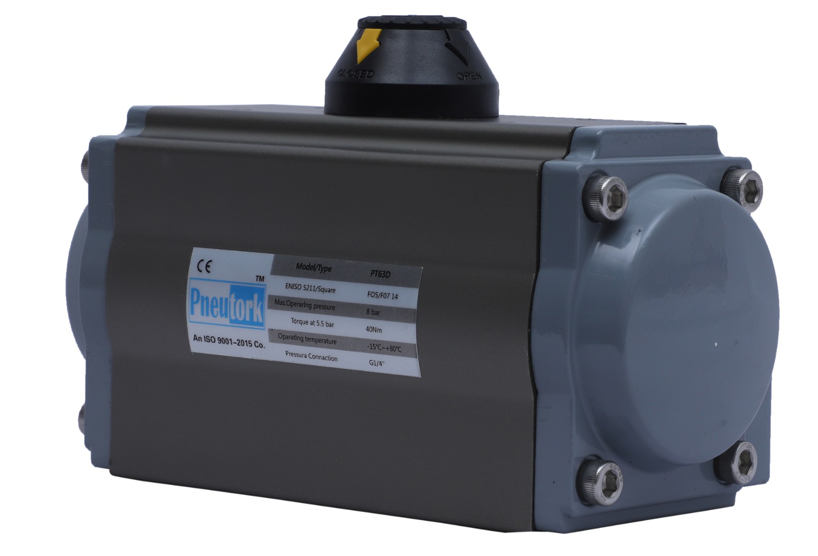
| Cylinder Block : | It is made of high quality aluminium alloy extrusion, the surface is coated with hard anodic oxidation and Teflon coating. |
| End Cover : | Aluminium alloy die casting, surface with anodic hardening treatment and metal polyester coating. |
| Piston : | Cast aluminum with hard oxidation. |
| Oper. Temp. Range : | -20°C to 80°C For Nitrile Seat (Depending On MOC) |
| Seat Leakege : | Tight Shut Off |
| Adjustment Bolt : | Two independent adjustment bolts realize accurate adjustment within ±5O of the angle of the valve opening and closing. |
| Piston Ring : | Use low friction and long life composite material, convenient reapir and replace. |
| Seal : | Use nitrile rubber under normal temperature, special seal is available according to the customer’s requirement for high temperature and low temperature. |
| Air connection : | It complies with NAMUR standard and can be direcly mounted with NAMUR standard solenoid valve. |
| Fastners : | All fastner are made of stainless steel. |
| Actuator model | 2.0 bar | 2.5bar | 3.0bar | 4.0bar | 4.5bar | 5.0bar | 5.5bar | 6.0bar | 7.0bar | 8.0bar |
|---|---|---|---|---|---|---|---|---|---|---|
| PT052D | 8 | 10 | 12 | 16 | 18 | 20 | 22 | 24 | 28 | 32 |
| PT063D | 15 | 18 | 22 | 29 | 33 | 36 | 40 | 44 | 51 | 58 |
| PT075D | 20 | 25 | 30 | 40 | 45 | 50 | 55 | 60 | 70 | 80 |
| PT083D | 31 | 39 | 47 | 63 | 70 | 78 | 86 | 94 | 111 | 125 |
| PT092D | 45 | 56 | 68 | 90 | 102 | 113 | 124 | 135 | 158 | 181 |
| PT105D | 66 | 83 | 99 | 132 | 149 | 165 | 182 | 198 | 231 | 264 |
| PT125D | 100 | 125 | 150 | 200 | 226 | 251 | 276 | 301 | 351 | 401 |
| PT140D | 171 | 214 | 256 | 342 | 385 | 427 | 470 | 513 | 598 | 684 |
| PT160D | 266 | 332 | 399 | 532 | 598 | 665 | 731 | 798 | 931 | 1064 |
| PT190D | 420 | 532 | 638 | 851 | 958 | 1064 | 1170 | 1277 | 1490 | 1702 |
| PT210D | 532 | 665 | 798 | 1064 | 1197 | 1330 | 1463 | 1596 | 1862 | 2128 |
| PT240D | 769 | 962 | 1154 | 1539 | 1731 | 1924 | 2116 | 2308 | 2693 | 3078 |
| PT270D | 1170 | 1462 | 1450 | 2339 | 2632 | 2924 | 3216 | 3509 | 4094 | 4679 |
| PT300D | 1526 | 1908 | 2289 | 3052 | 3434 | 3815 | 4197 | 4578 | 5341 | 6104 |
| PT350D | 2285 | 2856 | 3427 | 4570 | 5141 | 5712 | 6283 | 6854 | 7997 | 9139 |
| PT400D | 3256 | 4070 | 4884 | 6512 | 7326 | 8140 | 8954 | 9768 | 11396 | 13024 |
|
Actuator
MODEL |
SPRING
QUANTITY |
4.0 BAR | 5.0 BAR | 6.0 BAR | 7.0BAR | 8.0BAR | SPRING RETURN TORQUE | ||||||
|---|---|---|---|---|---|---|---|---|---|---|---|---|---|
|
0°
START |
90°
END |
0°
START |
90°
END |
0°
START |
90°
END |
0°
START |
90°
END |
0°
START |
90°
END |
0°
START |
90°
END |
||
| PT052S | 10 | 7.4 | 3.6 | 11.5 | 6.7 | 15.5 | 11.6 | 19.5 | 15.6 | / | / | 12.4 | 8.5 |
| PT063S | 10 | 1.4 | 8.2 | 22.8 | 15.6 | 30 | 22.8 | 37.3 | 30.1 | 44.7 | 37.4 | 20.9 | 13.7 |
| PT075S | 10 | 19 | 11.1 | 28.8 | 21.2 | 39 | 31.2 | 49.1 | 41.2 | 59.1 | 51.2 | 29 | 21.1 |
| PT083S | 10 | 31 | 16.6 | 46.7 | 32.3 | 62.4 | 48 | 78.1 | 63.7 | 93.8 | 79.3 | 46 | 31.6 |
| PT092S | 10 | 43.6 | 21.5 | 66.2 | 44.1 | 88.8 | 66.7 | 111.3 | 89.2 | 134 | 11.8 | 68.7 | 46.7 |
| PT105S | 10 | 68.9 | 33.4 | 102 | 66.5 | 135.1 | 99.6 | 161.8 | 123.1 | 201.2 | 165.7 | 98.4 | 63.3 |
| PT125S | 10 | 96 | 44 | 146 | 94 | 196 | 144 | 247 | 194 | 297 | 245 | 157 | 105 |
| PT140S | 10 | 170 | 84 | 256 | 169 | 314 | 255 | 427 | 340 | 512 | 426 | 258 | 172 |
| PT160S | 10 | 253 | 115 | 386 | 248 | 519 | 381 | 652 | 514 | 785 | 647 | 417 | 279 |
| PT190S | 10 | 451 | 233 | 664 | 446 | 877 | 658 | 1090 | 871 | 1302 | 1084 | 618 | 400 |
| PT210S | 10 | 514 | 304 | 780 | 570 | 1046 | 836 | 1312 | 1102 | 1578 | 1368 | 760 | 550 |
| PT240S | 10 | 718 | 431 | 1103 | 816 | 1488 | 1201 | 1872 | 1586 | 2257 | 1970 | 1108 | 821 |
| PT270S | 10 | 1220 | 767 | 1805 | 1352 | 2390 | 1937 | 2974 | 2521 | 3560 | 3107 | 1572 | 1119 |
| PT300S | 10 | 1430 | 695 | 2355 | 1693 | 2956 | 2221 | 3719 | 2984 | 4482 | 3747 | 2122 | 1460 |
| PT350S | 10 | 1963 | 787 | 3105 | 1929 | 4247 | 3071 | 5390 | 4214 | 6532 | 5356 | 3405 | 2346 |
| PT400S | 10 | 3012 | 1025 | 4640 | 2653 | 6268 | 4281 | 7895 | 5908 | 9523 | 7536 | 4938 | 3149 |
| SR.NO. | NAME |
QTY OF
EACH UNIT |
STANDARD MATERIAL |
MATERIAL OF
SELECTABLE |
|---|---|---|---|---|
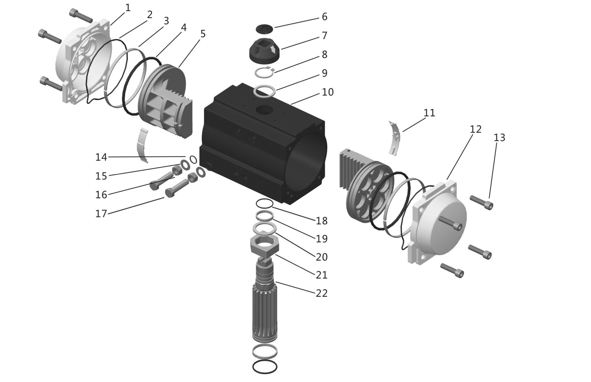
| 1 | Left cover | 1 | Aluminium Die Casting | - |
| 2 | “O” ring (cover) | 2 | NBR | FPM/Q |
| 3 | Piston Ring | 2 | POM | - |
| 4 | “O” ring (Piston) | 2 | NBR | FPM/Q |
| 5 | Piston | 2 | Aluminium Die Casting | - |
| 6 | Bolt | 1 | ABS | - |
| 7 | Main body of the Indicator | 1 | ABS | - |
| 8 | Shaft Ring | 1 | Stainless Steel | - |
| 9 | Gasket | 1 | POM | - |
| 10 | Block | 1 | Aluminum Extrusion | - |
| 11 | Guide Ring | 1 | PA66 | - |
| 12 | Right Cover | 1 | Aluminium Die Casting | - |
| 13 | End Cover Bolt | 8 | Stainless Steel | - |
| 14 | “O” ring (Adjustable bolt) | 2 | NBR | FPM/Q |
| 15 | Gasket | 2 | Stainless Steel | - |
| 16 | Nut | 2 | Stainless Steel | - |
| 17 | Adjustment Bolt | 2 | Stainless Steel | - |
| 18 | “O” Ring (at the top of the shaft) | 1 | NBR | - |
| 19 | Bearing (at the top of the shaft) | 1 | POM | - |
| 20 | Gasket | 1 | POM | - |
| 21 | Adjustment Cam | 1 | Carbonsteel | - |
| 22 | Output Shaft | 1 | Carbonsteel | - |
| 23 | Bearing (Output shaft bottom) | 1 | POM | - |
| 24 | “O” ring (output shaft bottom) | 1 | NBR | FPM/Q |
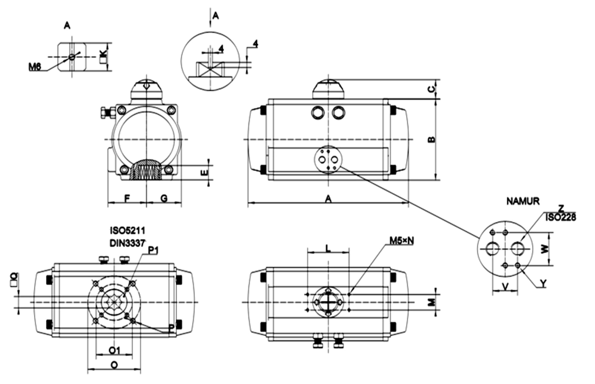
| Model | PT052 | PT063 | PT075 | PT083 | PT092 | PT105 | PT125 | PT140 | PT160 | PT190 | PT210 | PT240 | PT270 | PT300 | PT350 | PT400 |
|---|---|---|---|---|---|---|---|---|---|---|---|---|---|---|---|---|
|
ISO
FLANGE |
F03/F05 | F05/F07 | F05/F07 | F05/F07 | F05/F10 | F05/F10 | F05/F10 | F05/F12 | F05/F12 | F14 | F14 | F16 | F16 | F16 | F16/25 | F16/25 |
| A | 154 | 176 | 188 | 211 | 244 | 277 | 310 | 394 | 458 | 523 | 526 | 602 | 718 | 760 | 920 | 940 |
| B | 73 | 89 | 101 | 110 | 118 | 135 | 157 | 175 | 198 | 232 | 257 | 289 | 326 | 350 | 410 | 466 |
| C | 25 | 25 | 25 | 25 | 25 | 25 | 39 | 39 | 39 | 39 | 39 | 30 | 30 | 30 | 30 | 30 |
| E | 13 | 17 | 17 | 20 | 20 | 25 | 27 | 30 | 30 | 38 | 38 | 50 | 50 | 50 | 50 | 50 |
| F | 41 | 47 | 53 | 57 | 60 | 64 | 75 | 75 | 86 | 103 | 130 | 147 | 174 | 195 | 260 | 113 |
| G | 30 | 36 | 43 | 47 | 50 | 58 | 67 | 75 | 86 | 103 | 113 | 130 | 147 | 162 | 190 | 260 |
| L | 80 | 80 | 80 | 80 | 80 | 80 | 80 | 130 | 130 | 130 | 130 | 130 | 130 | 130 | 130 | 130 |
| M | 30 | 30 | 30 | 30 | 30 | 30 | 30 | 30 | 30 | 30 | 30 | 30 | 30 | 30 | 30 | 30 |
| N | 4-M5X9 | 4-M5X9 | 4-M5X9 | 4-M5X9 | 4-M5X9 | 4-M5X9 | 4-M5X9 | 4-M5X9 | 4-M5X9 | 4-M5X9 | 4-M5X9 | 4-M5X9 | 4-M5X9 | 4-M5X9 | 4-M5X9 | 4-M5X9 |
| 0 | 50 | - | - | - | - | - | - | - | - | - | - | - | - | - | - | - |
| P | 4-M6X9 | 4-M8X12 | 4-M8X12 | 4-M8X12 | 4-M10X15 | 4-M10X15 | 4-M10X15 | 4-M12X18 | 4-M12X18 | 4-M16X24 | 4-M16X24 | 4-M16X25 | 4-M16X25 | 4-M16X25 | 8-M16X24 | 8-M16X24 |
| 01 | 36 | 50 | 50 | 50 | 70 | 70 | 70 | 102 | 102 | - | - | - | - | - | - | - |
| P1 | 4-M5X8 | 4-M6X9 | 4-M6X9 | 4-M6X9 | 4-M8X12 | 4-M8X12 | 4-M8X12 | 4-M10X15 | 4-M10X15 | - | - | - | - | - | 4-M20X25 | 4-M20X25 |
| Q | 11 | 14 | 14 | 17 | 17 | 22 | 22 | 27 | 27 | 36 | 36 | 46 | 46 | 46 | 46 | 46 |
| V | 24 | 24 | 24 | 24 | 24 | 24 | 24 | 24 | 24 | 24 | 24 | 24 | 40 | 40 | 40 | 40 |
| W | 36 | 36 | 36 | 36 | 36 | 36 | 36 | 36 | 36 | 36 | 36 | 36 | 45 | 45 | 45 | 45 |
| Y | 4-M5X9 | 4-M5X9 | 4-M5X9 | 4-M5X9 | 4-M5X9 | 4-M5X9 | 4-M5X9 | 4-M5X9 | 4-M5X9 | 4-M5X9 | 4-M5X9 | 4-M5X9 | 4-M6X10 | 4-M6X10 | 4-M6X10 | 4-M6X10 |
| Z | G1/4” | G1/4” | G1/4” | G1/4” | G1/4” | G1/4” | G1/4” | G1/4” | G1/4” | G1/4” | G1/4” | G1/4” | G1/2” | G1/2” | G1/2” | G1/2” |
Reach out for tailored solutions. Our team is ready to assist. Submit an inquiry and experience excellence in valve automation solutions.