
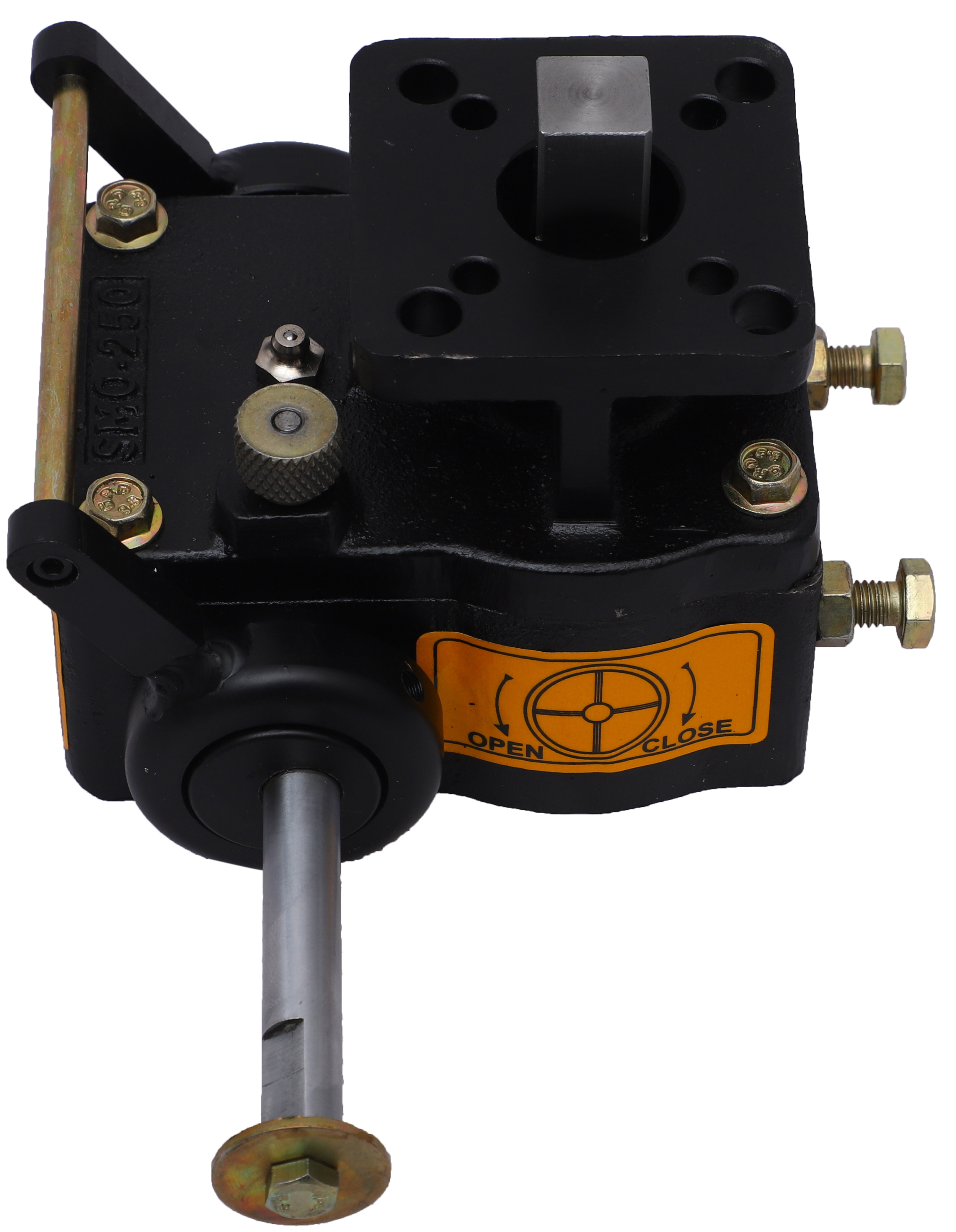
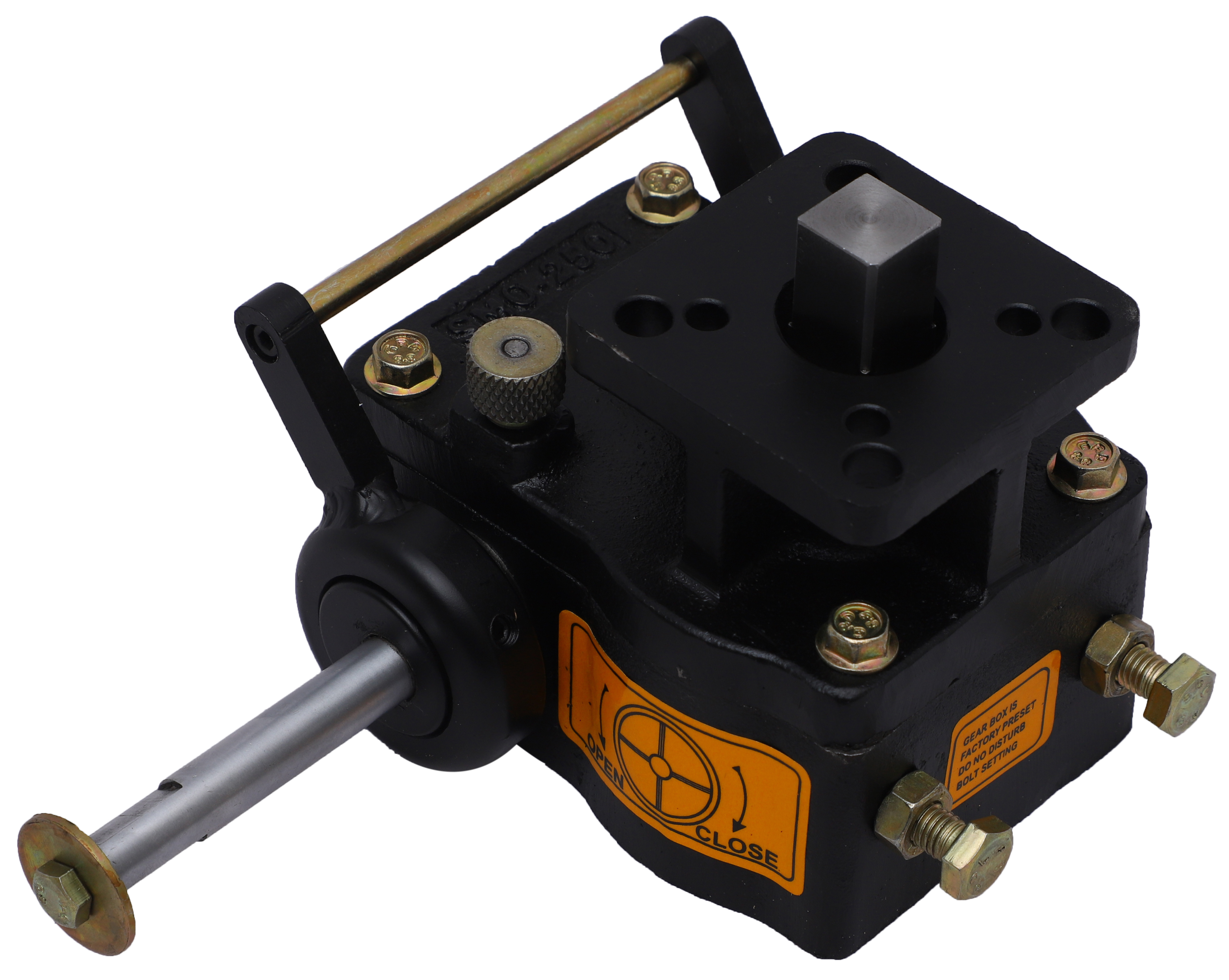
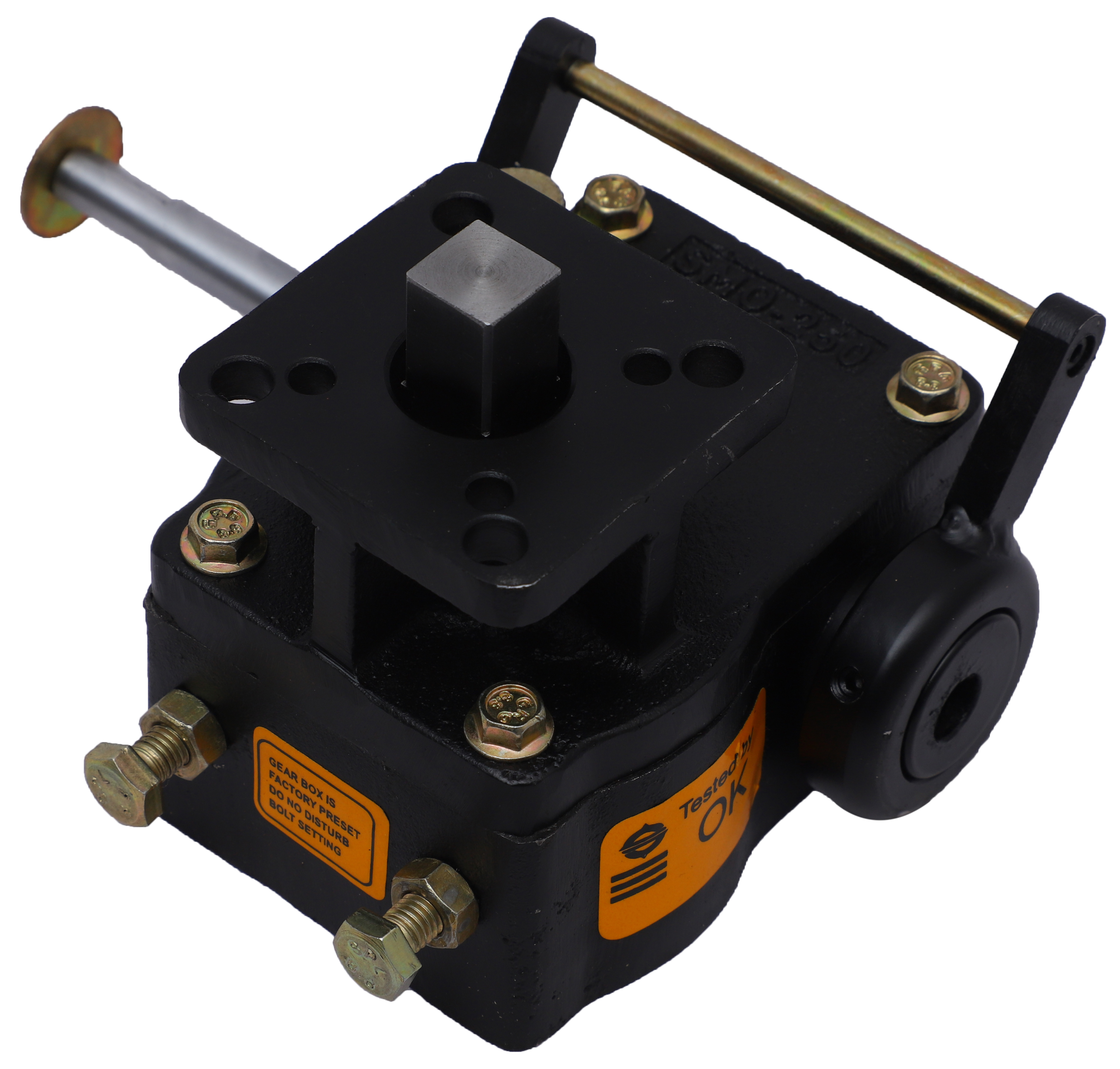
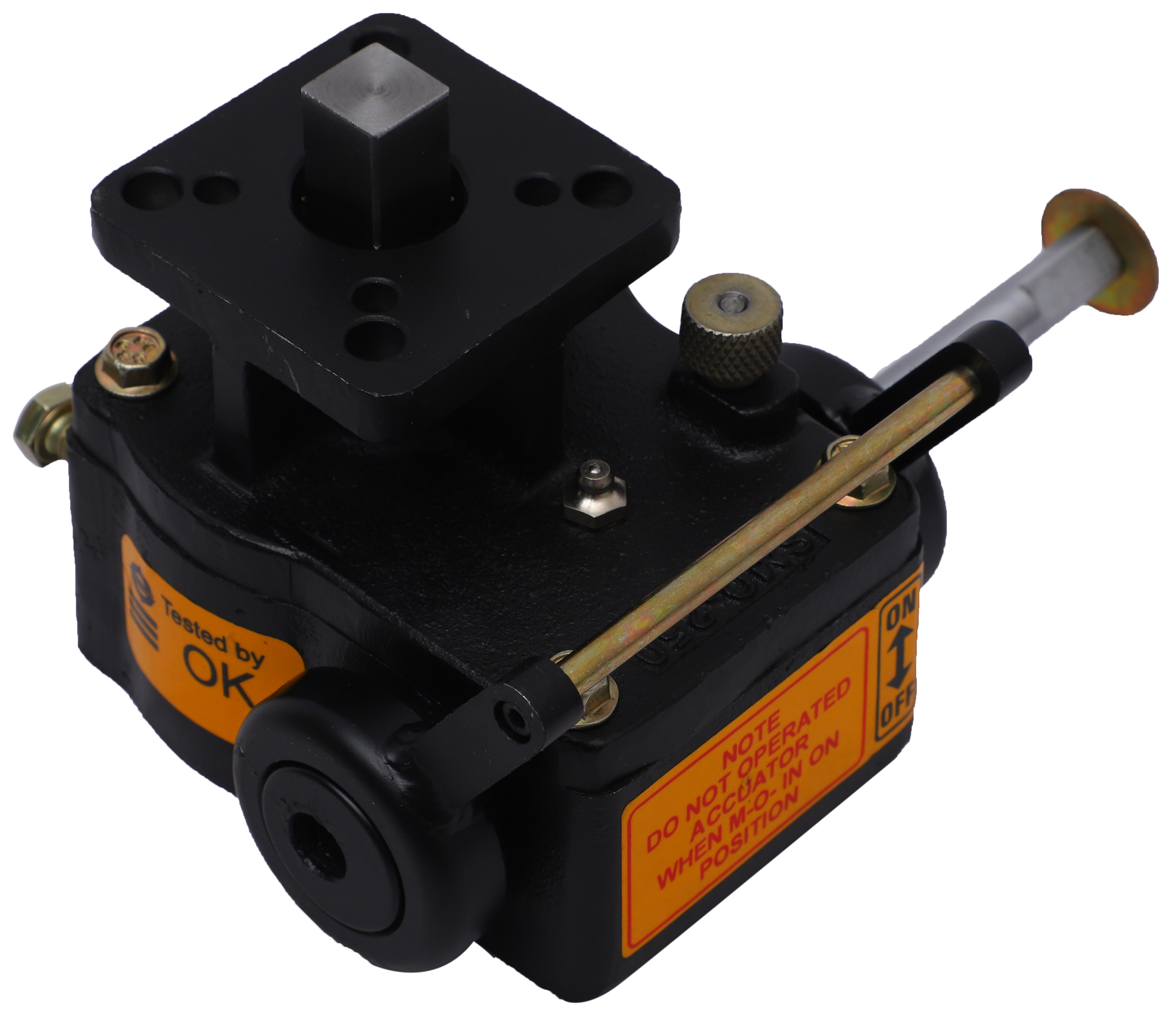
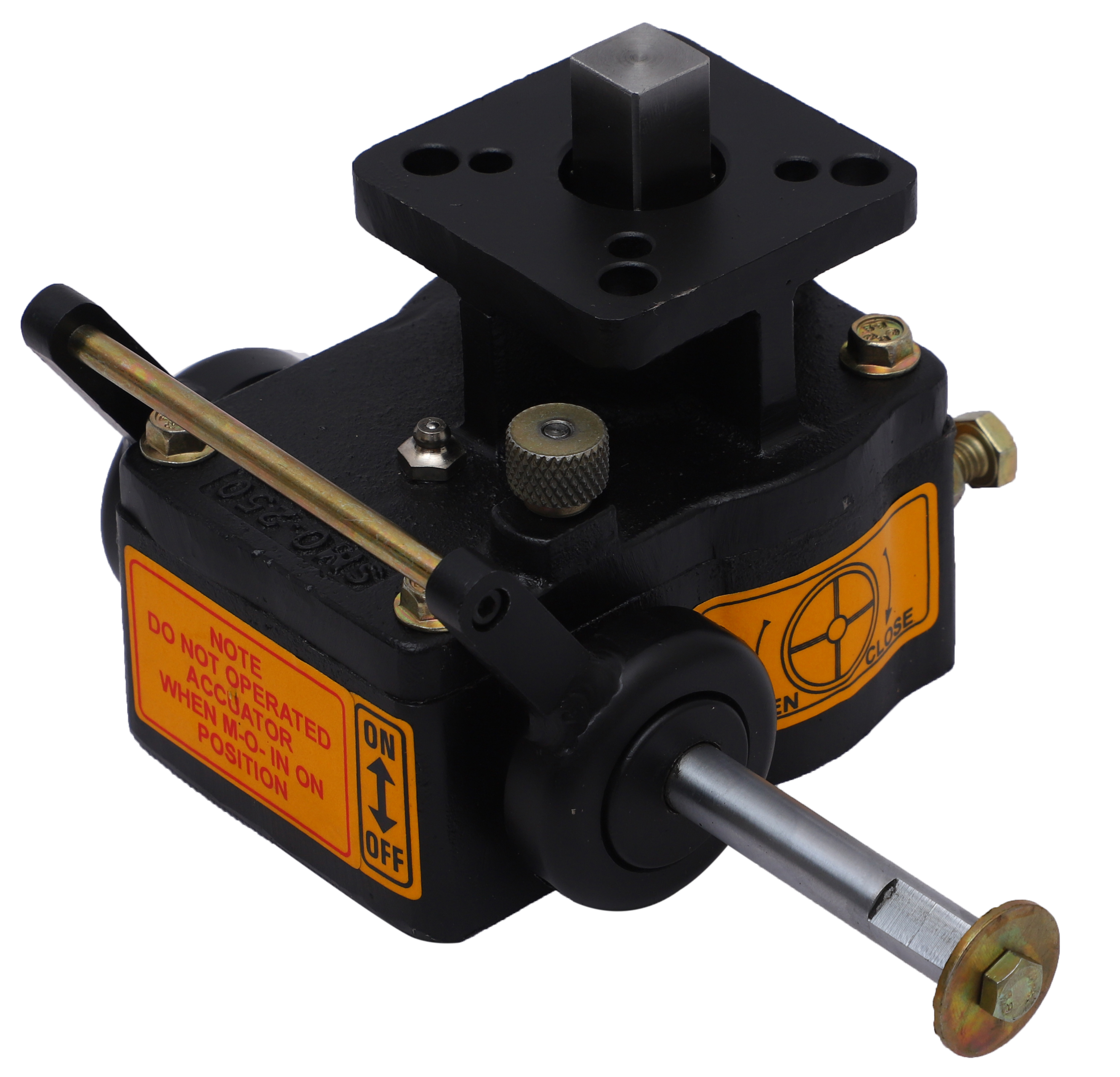
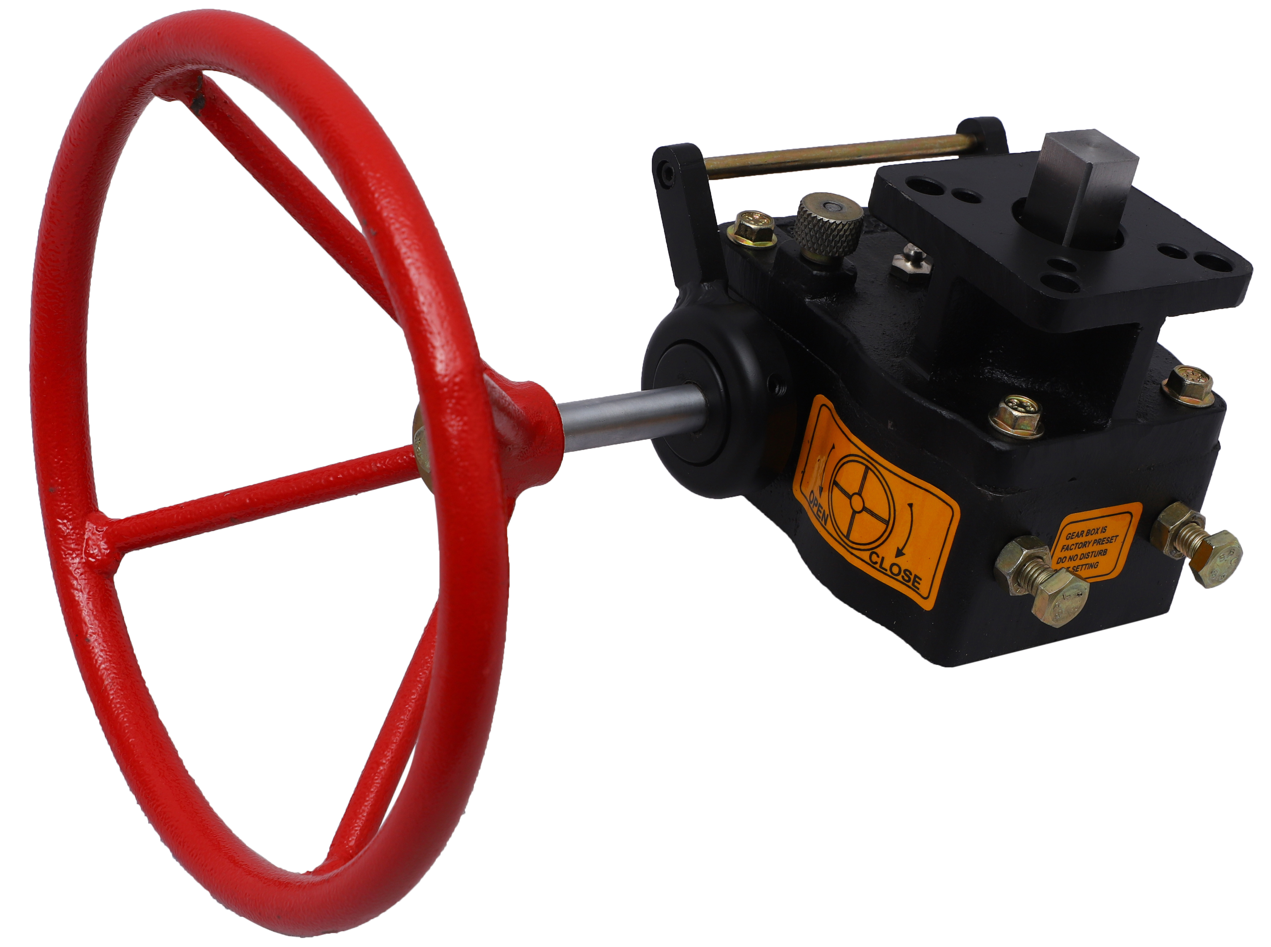
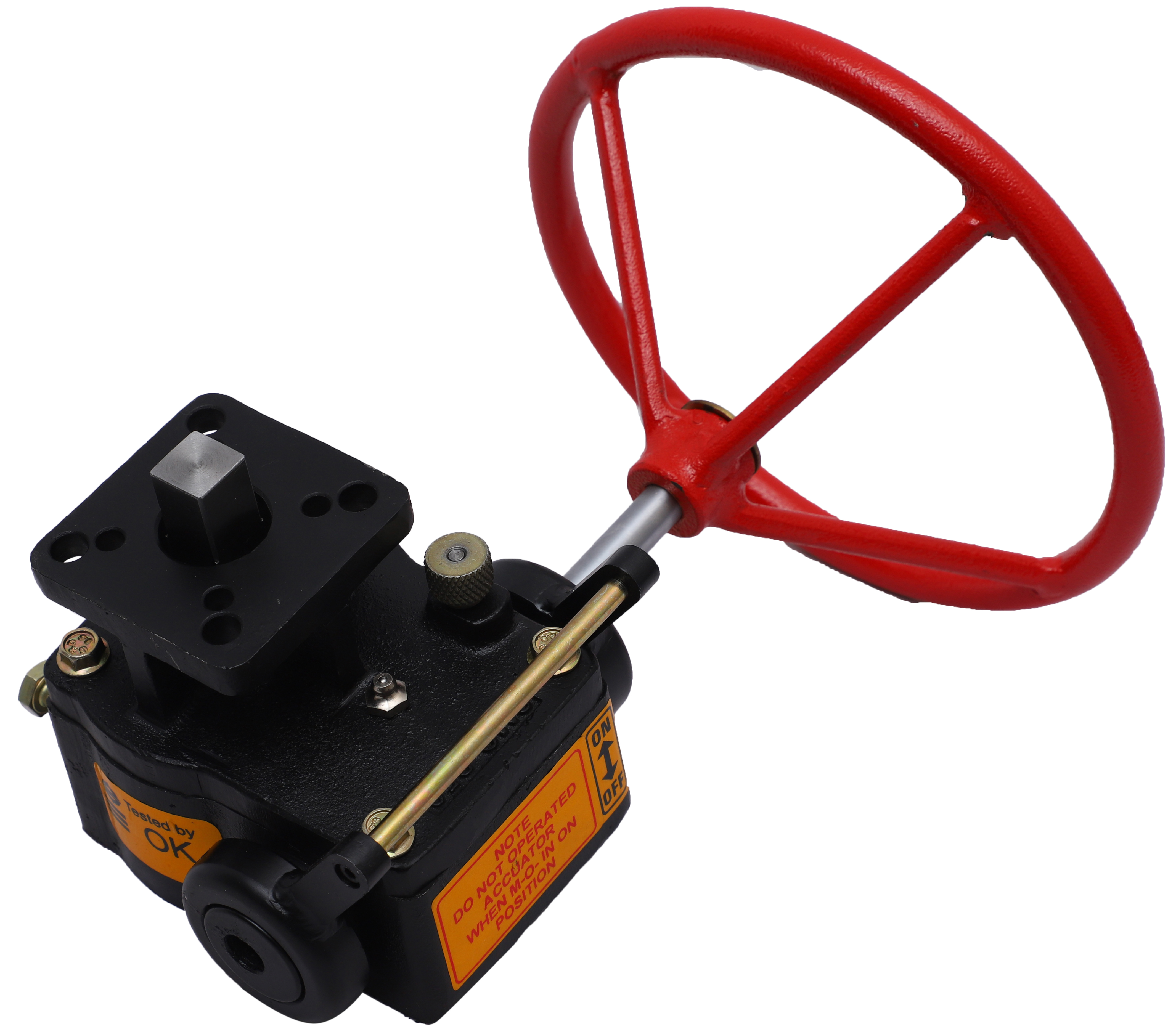
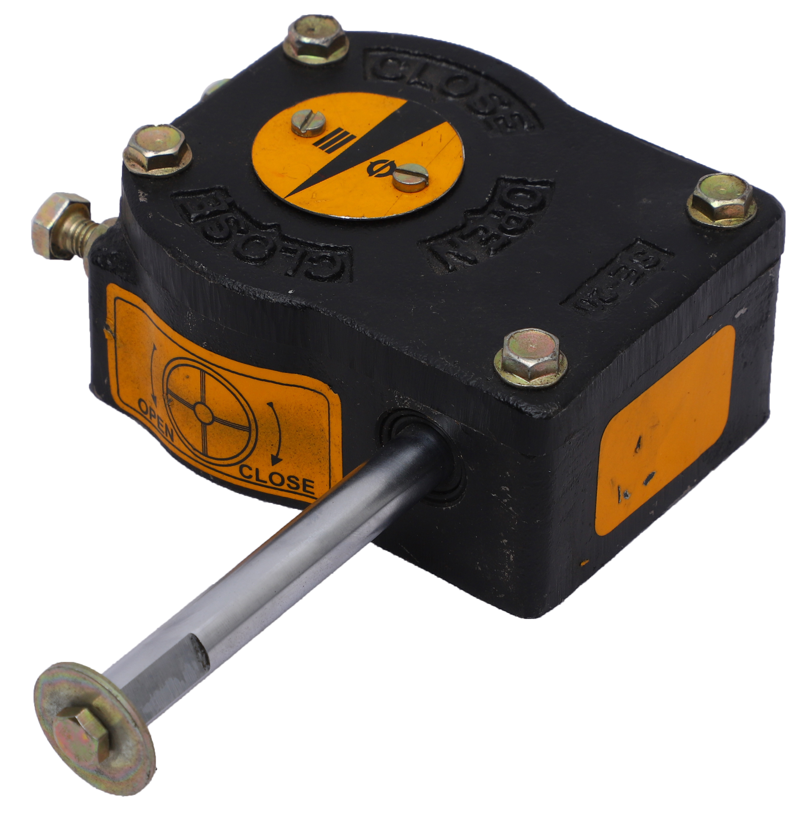
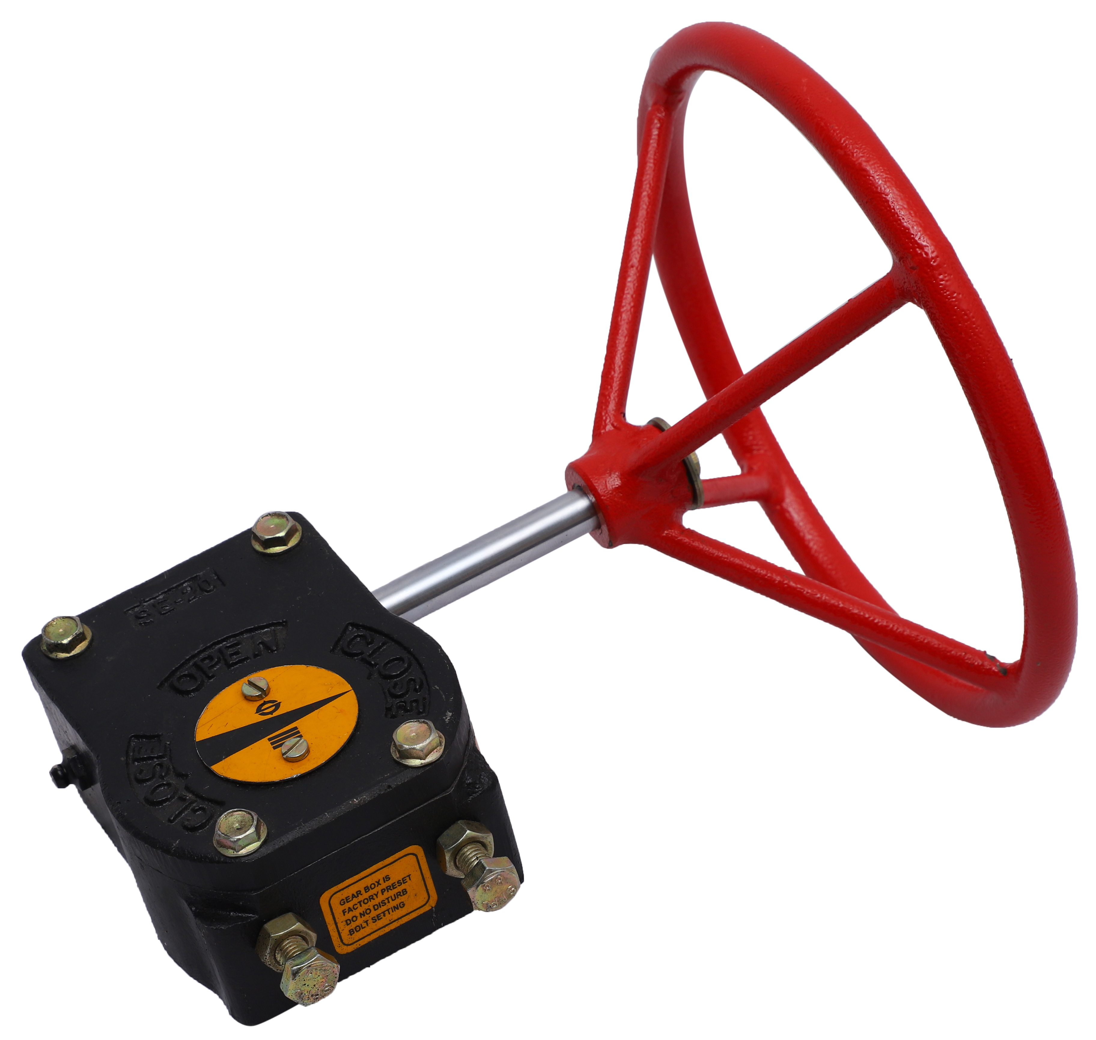
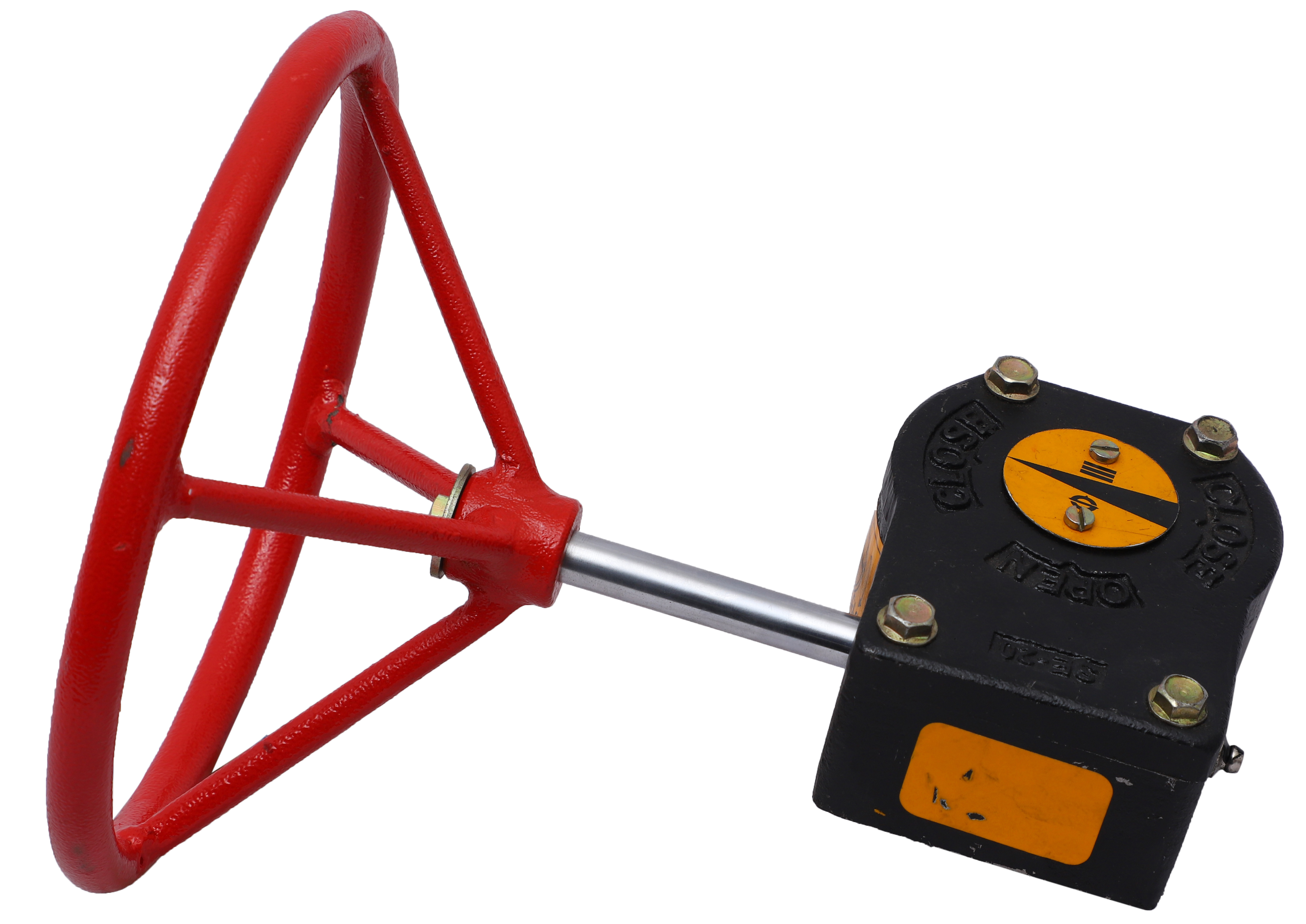
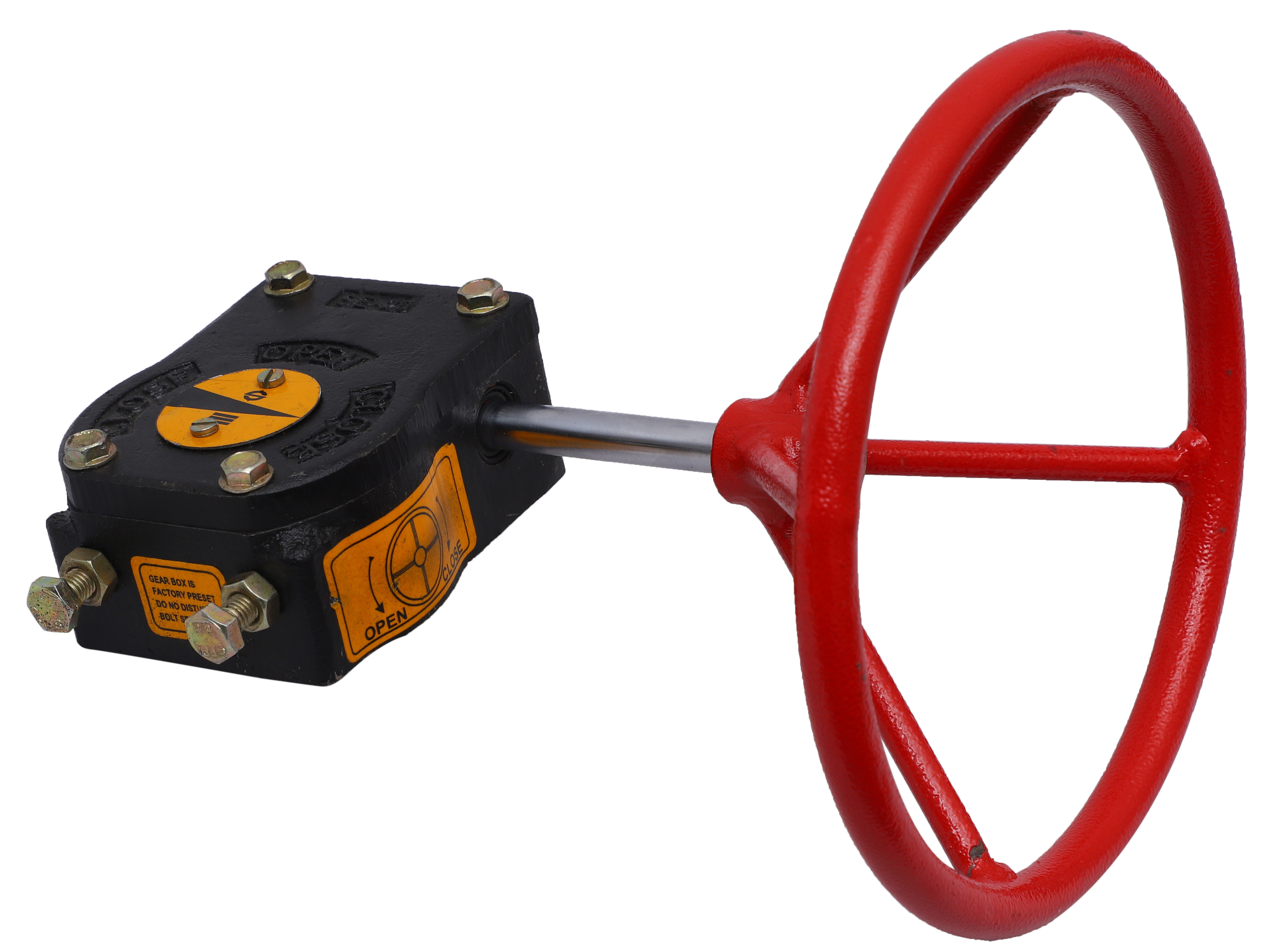
Pneutork Manual Over-Ride Worm Gear boxes are used with pneumatic, hydraulic and back-drivable electric actuators. These products are sandwich mounted as part of an automated valve package to provide manual operation to the valve and manually over-riding pneumatic actuators in case of loss in plants air supply, power gas, hydraulic fluid power or electricity occurs. These gearboxes are engineered and designed for higher efficiencies and lower efforts on hand wheel which are used with valves and dampers for quarter turn rotary applications that comes with thirteen different frames and spur combinations to provide output torque range from 60 to 5,000 Nm. These gearboxes are designed with standard ISO 5211 mounting dimensions for mounting to valve & actuator
| No. | Name of Part | Material Specification |
|---|---|---|
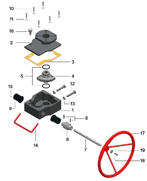
| 1 | Body | Cast Iron (Gr. FG 260) |
| 2 | Cover | Cast Iron (Gr. FG 260) |
| 3 | Body Gasket | Rubber Cork |
| 4 | Worm Wheel | SG Iron (Gr. 500/7) |
| 5 | O-Ring (For Worm Wheel) | NBR |
| 6 | Worm | EN8 |
| 7 | Shaft | EN8 |
| 8 | Dowel Pin (for Worm & Shaft) | SS304 |
| 9 | Eccentric Bush | CI |
| 10 | Hex Bolt (for Body & Cover) | MS (Zinc Plated) |
| 11 | Hex Bolt Washer (for Body & Cover) | MS (Zinc Plated) |
| 12 | Adjustable Hex Bolt | MS (Zinc Plated) |
| 13 | Adjustable Hex Nut | MS (Zinc Plated) |
| 14 | Clutch Lever | MS |
| 15 | Grub Screw (for Clutch & Bush) | Spring Steel |
| 16 | Clutch (knob assembly) | MS (Zinc Plated) |
| 17 | Hand Wheel | MS (Powder Coated) |
| 18 | Bot for Hand Wheel | MS (Zinc Plated) |
| 19 | Washer for Hand Wheel | MS (Zinc Plated) |
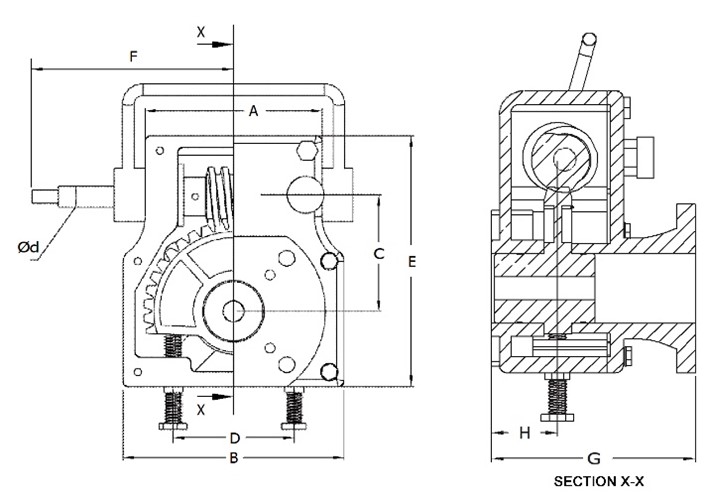
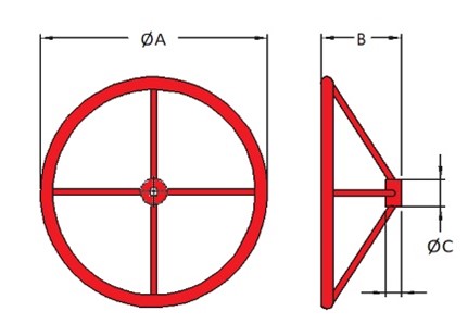
| Model | Rated Output Torque ±10% (Nm) | Mechanical Advantage | Gear Ratio | Turns To Close | ISO 5211 Mounting | Square On I/P Shaft | Hand Wheel ∅ (mm) | Dimensions | WHEEL DIMENSION | |||||||||||
|---|---|---|---|---|---|---|---|---|---|---|---|---|---|---|---|---|---|---|---|---|
| A | B | C | D | E | F | G | ∅d | Hand Wheel Dia ∅A | Height ∅G | Bush OD ∅C | Bush Length L | No. of Spokes | ||||||||
| MOR-100 | 100 | 8 | 36:1 | 9 | F05, F07 | 9X9 | 180 | 83 | 100 | 52.50 | 50 | 121 | 128.5 | 101 | 12 | 180 | 70 | 30 | 18 | 3 |
| MOR-250 | 250 | 8 | 36:1 | 9 | F05, F07 | 9X9 | 180 | 83 | 100 | 52.50 | 50 | 121 | 128.5 | 101 | 12 | 250 | 85 | 30 | 18 | 3 |
| MOR-450 | 450 | 8.4 | 38:1 | 9.5 | F07, F10 | 11X11 | 250 | 120 | 150 | 78.90 | 58 | 170 | 137 | 123.5 | 14 | 300 | 90 | 30 | 18 | 4 |
| MOR-750 | 750 | 10 | 45:1 | 11.5 | F07, F10, F12 | 11X11 | 350 | 118 | 169 | 89.50 | 62 | 192 | 194.6 | 126 | 16 | 350 | 110 | 30 | 18 | 4 |
| MOR-1000 | 1000 | 13.2 | 60:1 | 15 | F10, F12, F14 | 11X11 | 350 | 140 | 216 | 111.70 | 150 | 214 | 208 | 126 | 16 | 450 | 145 | 40 | 30 | 4 |
| MOR-1500 | 1500 | 16.5 | 76:1 | 19 | F10, F12, F14 | 14X14 | 350 | 180 | 270 | 136.50 | 200 | 246 | 187 | 186 | 25 | 500 | 145 | 40 | 30 | 4 |
| MOR-3500 | 3500 | 16 | 72:1 | 18 | F12, F14F, F16 | 17X17 | 450 | 232 | 340 | 173 | 220 | 313 | 230 | 186 | 25 | 500 | 145 | 40 | 30 | 4 |
| MOR-5000 | 5000 | 18 | 90:1 | 20 | F16, F20 | 17X17 | 600 | 306 | 435 | 209 | 250 | 385 | 380 | 180 | 25 | 600 | 150 | 40 | 30 | 5 |
Reach out for tailored solutions. Our team is ready to assist. Submit an inquiry and experience excellence in valve automation solutions.