
The prerequisite for triggering an explosion is that the explosive material must be mixed with oxygen to a certain extent to cause a chemical reaction under appropriate ignition conditions. If the speed of reaction exceeds the speed of sound, it is defined as an explosion
The explosive mixture that accumulates to a certain degree explodes suddenly and causes destruction effect in the form of explosion wave.
An explosion can be prevented if any one of the above three conditions is restricted. At many service sites, the presence of explosive substances and oxygen is difficult to avoid, so the source of ignition must be limited. Electrical equipment is a potential source of ignition. When the machine is running, it causes surface temperature rise, electrostatic release or sparks caused by instantaneous current.
The explosion-proof electrical equipment is designed to avoid excessive surface temperature and spark during its operation. Therefore, explosion-proof electrical equipment will not become a potential source of ignition.
Generally, electrical equipment used in explosive gas environments can be divided into two categories
Class I Electrical equipment for coal mine
Class II Electrical equipment for explosive gas environments other than coal mine
For Class II electrical equipment, explosive gas can be divided into three explosive levels: IIA,IIB and IIC according to the maximum test safety gap (flameproof type) and minimum test ignition current (intramentally safe type). Class IIB equipment can be applied to the service conditions of IIA equipment, and class IIC equipment can be applied to the service conditions of IIA and IIB equipment.
For Class II electrical equipment, according to the maximum allowable surface temperature can be divided into T1 (450 ° C), T2 (300 ° C), T4(135 ° C), T5(100 ° C), T6 (85 ° C) six temperature groups, and the high temperature group equipment can be applied to the use of low group conditions.
More than 90% of the explosive gases are contained in the IIA, IIB explosive levels and T1-T4 temperature groups.
There are various ways to make electrical equipment suitable for explosive environments, and these methods are described in detail in GB3836,ICE60079, EN50014 and other standards.
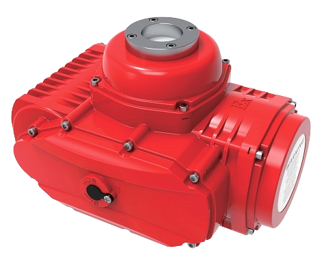
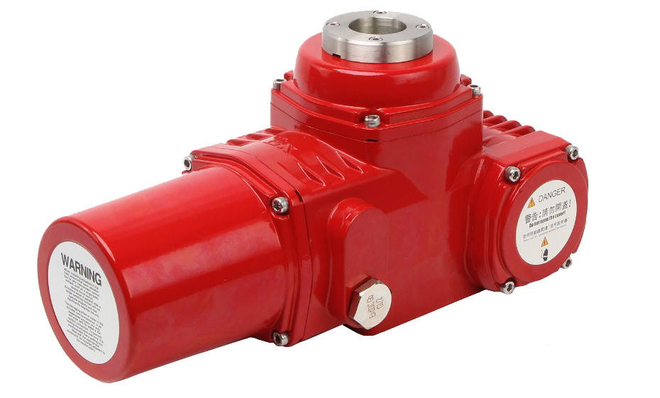
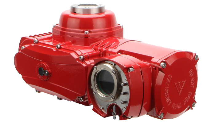
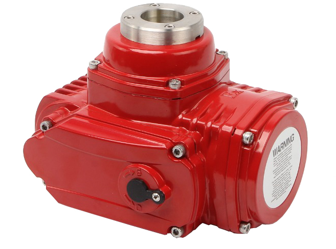
PVQ series explosion-proof electric actuators are manufactured in accordance with the explosion-proof type of "flameproof type "(Exd), in line with GB3836.1-2010, GB3836.2-2010 standard requirements.
The flameproof actuators allow explosions to occur inside the equipment. The flameproof surface of the housing is designed to prevent the internal spark or explosion carrier from contacting the outside world. Appropriate flameproof surface clearance and sufficient length of the flameproof surface ensure this. At the same time, the sturdy shell can withstand the high pressure generated by the internal explosion without being damaged
The following parts of PVQ series actuators are designed and
manufactured
according to flameproof standards.
Motor chamber Electrical element chamber Wiring
chamber
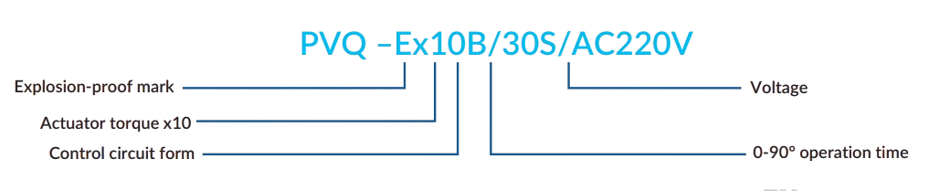
AUQ explosion-proof series electric actuator grade: ExdIICT6Gb
Ex-Explosion-proof marking
D-Explosion-proof type: flameproof
II-Equipment type: other gas environments except coal mine
C-Explosive level, this level determines the size (length and clearance) of each flameproof joint of the actuator.
T6-Temperature class,the maximum allowable surface temperature of the actuator is 85° C
Gb-Explosion protection level of equipment
Installation, commissioning, maintenance, repair, and replacement shall be carried out by qualified explosion-proof professionals who have been trained, and shall strictly comply with the requirements of the electrical equipment (operation manual).
|
Actuator
Model |
Max Output
Torque N-M |
Operating Time To 90° S
AC DC |
Motor (W)
AC DC |
Single Phase Rated Current (A)
AC24V AC110V AC220V AC380V DC24V DC220V |
Weight
Kg |
|||||||
|---|---|---|---|---|---|---|---|---|---|---|---|---|
| PVQOO5 | 5O | 30 | 10 | 15 | 15 | 2.2 | 0.48 | 0.24 | 0.16 | 1.2 | 0.15 | 3.5 |
| PVQO1O | 100 | 30 | 10 | 30 | 25 | 3.6 | 0.8 | 0.4 | 0.22 | 1.6 | 0.2 | 6 |
| PVQO15 | 15O | 30 | 10 | 30 | 25 | 3.6 | 0.8 | 0.4 | 0.22 | 1.6 | 0.2 | 6 |
| PVQO2O | 200 | 30 | 15 | 90 | 70 | 9 | 1.8 | 0.92 | 0.53 | 2.6 | 2.3 | 12.2 |
| PTL-015 | 109 | 80 | 45 | 126 | 67 | 85 | 114 | 100 | 100 | 90 | 50 | 50 |
| PVQO4O | 400 | 30 | 15 | 90 | 70 | 9 | 1.8 | 0.92 | 0.53 | 2.6 | 0.3 | 12.5 |
| PVQO6O | 600 | 30 | 15 | 90 | 70 | 9 | 1.8 | 0.92 | 0.53 | 4.5 | 0.5 | 12.5 |
| PVQ1OO | 1000 | 40 | 25 | 130 | 130 | 12 | 2.2 | 1.1 | 0.6 | 5.0 | 0.6 | 12.5 |
| PVQ2OO | 2000 | 90 | 50 | 300 | 300 | 17 | 2.8 | 1.4 | 0.8 | 6.0 | 0.8 | 21 |
| PVQ3OO | 3OOO | 90 | 50 | 300 | 300 | 17 | 2.8 | 1.4 | 0.8 | 6.0 | 0.8 | 21 |
| Explosive Level | Temperature Group | |||||
|---|---|---|---|---|---|---|
| T1 (450℃) | T2 (300℃) | T3 (200℃) | T4 (135℃) | T5 (100℃) | T6 (85℃) | |
| IIA |
Acetone
Ethane Phenol Acetic acid Methanol Propane |
Ethyl alcohol
Butane Butanol Ethylene 2 ethane |
Benzene
Diesel Aircraft fuel Fuel Ethane |
Acetaldehyde | ||
| IIB | Gas |
Ethylene
Ethylene oxide |
Diethyl ether | |||
| IIC | Hydrogen | Acetylene | Carbon disulphide | |||
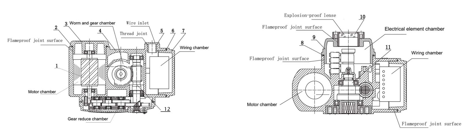
| SR.NO. | NAME | MATERIAL |
|---|---|---|
| 1 | Motor rotor shaft | 40Cr |
| 2 | O ring | NBR |
| 3 | Motor cover | ADC12 |
| 4 | Shell | ADC12 |
| 5 | Explosion-proof plug | Nickel plated brass |
| 6 | O ring | NBR |
| 7 | Terminal cover | ADC12 |
| 8 | O ring | NBR |
| 9 | Upper cover | ADC12 |
| 10 | Lense | Soda-lime glass |
| 11 | Output shaft | Nickel plated 40Cr |
| 12 | Worm | #45 steel |
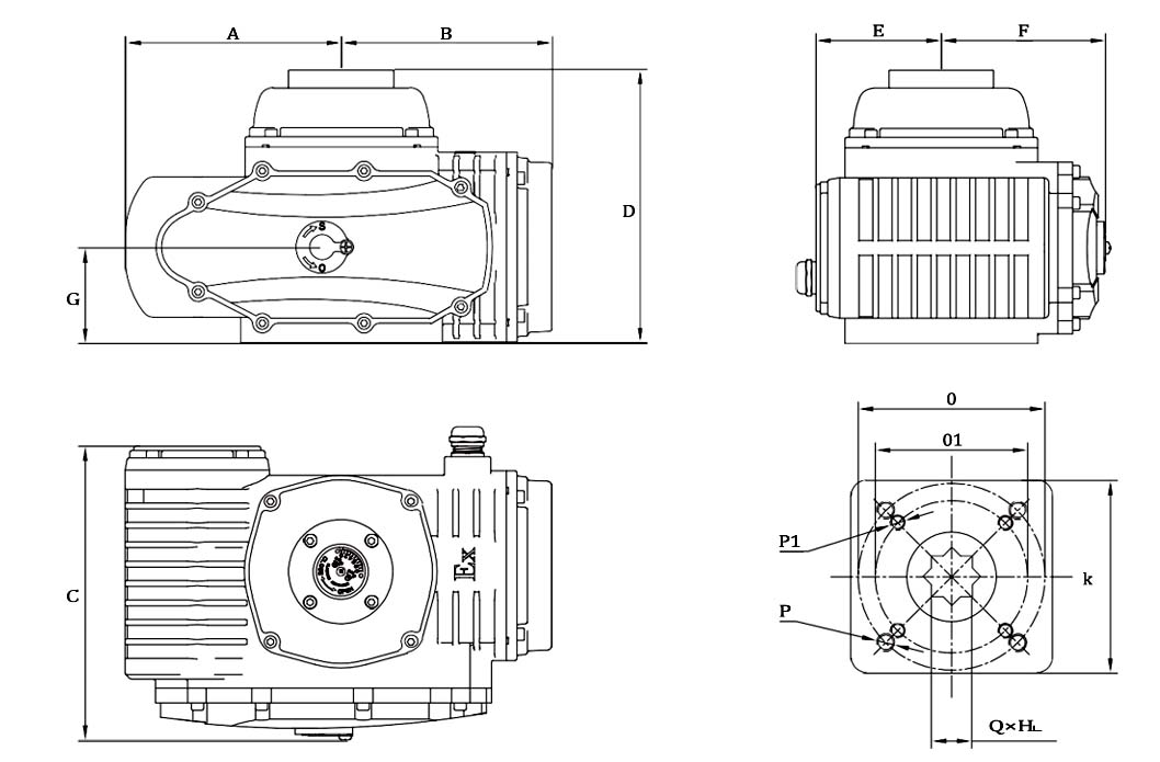
| Model | A | B | C | D | E | F | G | K | O | P | 01 | P1 | QxH |
|---|---|---|---|---|---|---|---|---|---|---|---|---|---|
| PVQ-005 | 90 | 102 | 146 | 142 | 66 | 77 | 42 | 80 | 70 | 4-M8 | 50 | 4-M6 | 14×19 |
| PVQ-010 | 106 | 110 | 154 | 155 | 72 | 79 | 45 | 95 | 70 | 4-M8 | 50 | 4-M6 | 17×22 |
| PVQ-015 | 106 | 110 | 154 | 155 | 72 | 79 | 45 | 95 | 70 | 4-M8 | 50 | 4-M6 | 17×22 |
| PVQ-020 | 144 | 141 | 197 | 183 | 84 | 110 | 64 | 129 | 125 | 4-M12 | 102 | 4-M10 | 22×24 |
| PVQ-040 | 144 | 141 | 197 | 183 | 84 | 110 | 64 | 129 | 125 | 4-M12 | 102 | 4-M10 | 22×24 |
| PVQ-060 | 144 | 141 | 197 | 183 | 84 | 110 | 64 | 129 | 125 | 4-M12 | 102 | 4-M10 | 22×24 |
| PVQ-100 | 144 | 141 | 197 | 183 | 84 | 110 | 64 | 129 | 125 | 4-M12 | 102 | 4-M10 | 22×24 |
| PVQ-200 | 175 | 170 | 227 | 211 | 99 | 125 | 73 | 150 | 140 | 4-M16 | 102 | 4-M10 | 27×29 |
| PVQ-300 | 175 | 170 | 227 | 211 | 99 | 125 | 73 | 150 | 140 | 4-M16 | 102 | 4-M10 | 36×39 |
|
ON/OFF Actuator
A/B/D/G/H Control circuit |
ON/OFF type only has full open and full off limit position, if necessary, can preset the middle position (B/D/G/H). Upon appropriate instruction, the actuator will drive the valve to a fully open or fully closed or intermediate position. |
|---|---|
|
Feedback Actuator
C/D/F Control circuit |
In the process of driving the valve, the actuator feedback valve position signal to the central control system at the same time. C/D feedback resistance valve position signal, F feedback analog valve position signal. |
|
Modulating Actuator
E Control circuit |
The servo controller is placed inside the actuator and drives the valve to the appropriate opening position according to the change of the controlled variables (flow, pressure, temperature, liquid level) in the pipeline and accepts the instructions of the central control system. |
| Motor |
Due to the working characteristics of the valve, it is required that the
actuator in the valve
open, close, and any position in the middle have full load starting
capacity, which requires
themotor of the actuator has a higher starting torque. At the same time, due
to the flow
(opening) adjustment needs, the motor must also have a small moment of
inertia. PVA
series electric actuator motors are specially designed for these
requirements.
When the actuator is stuck, the temperature of the motor will rise rapidly. When the motor temperature rises to 105°C, the PTC overheat protector embedded in the motor windings will cut off the circuit to protect the motor and the control system. When the temperature of the motor drops to 80-90°C, the circuit will be connected again. |
| Servo Controller | Unique circuit design, all imported industrial electronic components, the use of modern circuit board manufacturing process, ensure the servo controller of AUQ actuator of high quality and high reliability. The whole circuit board is protected by resin plastic seal, anti-seismic and moisture-proof performance is better. Unique electronic braking function, making the actuator positioning without vibration, damping characteristics for 0 cycles (no more than 3.5 cycles according to the standard) |
|---|---|
| Electrical Limit Stroke Micro adjustment Device | Only a straight screwdriver is needed to easily adjust the electric limit stroke of the actuator in the open and close directions. At the same time, the unique micro adjustment function makes the adjustment of electric limit stroke more accurate. |
| Electrical Limit Function |
Electrical stroke limit function: when the actuator reaches the full open,
full close limit position or
the set intermediate position, the built-in electric limit switch will cut
off the circuit to protect the
actuator.
Output shaft mechanical limit function: when the electric stroke limit function: when the electric stroke limit function fails, the actuator output shaft will be locked by the mechanical limit device to protect the valve from damage The diagram shows the position relationship between electrical limit and mechanical limit |
| Overtorque protection function (optional) | When the valve is stuck in the working process (middle position) due to impurities in the pipeline foreign matter or other reasons, the output torque of the actuator will increase rapidly, reach the set value (jump torque), the torque switch will disconnect the circuit, so as to protect the valve and actuator from damage. |
| Heating dehumidfication function (optional) | The electrical chamber of PVQ actuator can be equipped with PTC electronic heating element, which is used in the place where the temperature difference between day and night is large and relatively humid, to prevent the damage of electrical components caused by condensation and frost. The heater is continuous working and charged, even if the actuator is not running. |
| Torque range | 50-3000Nm Optional AUM series for larger torque or faster opening |
|---|---|
| Body material | Aluminium Die-casting |
| Position indicator | The valve position dial shows continuous position changes even when power is off. |
| External protection against corrosion | Coating |
|---|---|
| Polyester powder coating in accordance with GBT 18593-2001 standard Optional protection against corrosive conditions | |
| Screws are stainless steel |
| Stroke | 90° standard (90° ~270° optional) |
|---|---|
| Limit switch | 2xOpen/Close, SPDT, 250VAC10A |
| Auxiliary limit switch | 2xOpen/Close, SPDT, 250VAC10A |
| Mechanical limit | 2 internal adjusting bolts |
| Self-lock device | Self-lock by worm and worm gear |
|---|---|
| Mounting Flange | ISO5211 |
| Output shaft | Inner octagonal type, connect directly to the valve horizontally or vertically |
| Shock resistance | XYZ10g.o.2~34Hz, 30 minutes |
| Lubrication | Aluminium-base grease (EP type) |
| Manual operate | Mechanical clutch |
| Spanner | Reliable, labor-saving and small |
| Motor Power | 24/110/220VAC 1Phase, 380/440VAC 3Phase, 12/24/220VDC |
|---|---|
| Control Power | 24/110/220VAC 1Phase, 380/440VAC 3Phase, 12/24/220VDC |
| Motor | Squirrel-cage asynchronous motor, insulation class H |
| Fail protection/Operating temperature | Built-in thermal protection, open 120 °C±5 °C/close 97°C±5°C |
| Heater | 25~30W (220VAC) Prevent Condensation |
| Wiring Hole | 2 x G1/2” |
| 2Actuator meets the following requirements | |
| Conformance with | 2014/30/EU EMC 2014/35/EU LVD |
| The following coordination criteria | |
| General emission standard for industrial environment EN 61000-6-4 | |
| General anti-interference standard for industrial environment EN 61000-6-4 | |
| Electric rotating machinery standard EN 60034-1 |
Reach out for tailored solutions. Our team is ready to assist. Submit an inquiry and experience excellence in valve automation solutions.